I was just about to finish another blog post on MPLS when I got a question from a colleague about Junos routing tables. He was confused as to how to interpret the output of a basic Juniper routing table. I spent some time trying to find some resource to point him at – and was amazed at how hard it was to find anything that answered his questions specifically. Sure, there are lots of blogs and articles that explain RIB/FIB separation, but I couldn’t find any that backed it up with examples and the level of detail he was looking for. So while this is not meant to be exhaustive – I hope it might provide you some details about how to interpret the output of some of the more popular show commands. This might be especially relevant for those of you who might be coming from more of a Cisco background (like myself a number of years ago) as there are significant differences between the two vendors in this area.
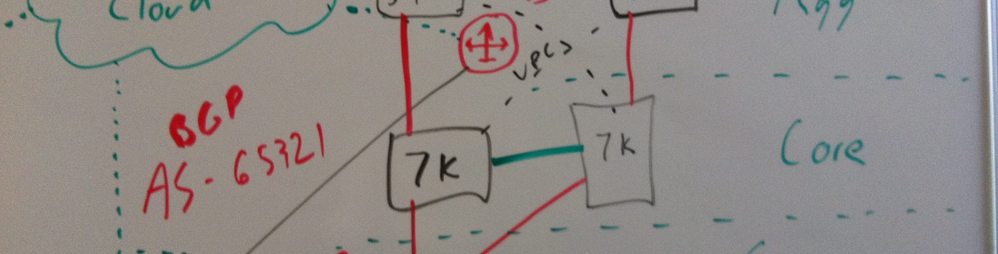
Let’s start with a basic lab that looks a lot like the one I’ve been using in the previous MPLS posts…

For the sake of focusing on the real topic of this post, I’m not going to dive into the base configuration but beyond configuring the IP address on the interfaces shown on the diagram, the base configuration includes enabling all interfaces (loopbacks too) with OSPF. So let’s begin by looking at the output of vMX1’s global (inet.0) routing table…
[email protected]> show route table inet.0

inet.0: 17 destinations, 17 routes (17 active, 0 holddown, 0 hidden)
+ = Active Route, - = Last Active, * = Both

1.1.1.1/32         *[Direct/0] 1d 00:07:39
                    > via lo0.0
2.2.2.2/32         *[OSPF/10] 1d 00:04:07, metric 1
                    > to 10.1.1.1 via ge-0/0/1.0
3.3.3.3/32         *[OSPF/10] 1d 00:04:07, metric 2
                    > to 10.1.1.1 via ge-0/0/1.0
                      to 10.1.1.7 via ge-0/0/2.0
4.4.4.4/32         *[OSPF/10] 1d 00:04:17, metric 1
                    > to 10.1.1.7 via ge-0/0/2.0
10.1.1.0/31        *[Direct/0] 1d 00:05:19
                    > via ge-0/0/1.0
10.1.1.0/32        *[Local/0] 1d 00:05:19
                      Local via ge-0/0/1.0
10.1.1.2/31        *[OSPF/10] 1d 00:04:07, metric 2
                    > to 10.1.1.1 via ge-0/0/1.0
10.1.1.4/31        *[OSPF/10] 1d 00:04:17, metric 2
                    > to 10.1.1.7 via ge-0/0/2.0
10.1.1.6/31        *[Direct/0] 1d 00:05:19
                    > via ge-0/0/2.0
10.1.1.6/32        *[Local/0] 1d 00:05:19
                      Local via ge-0/0/2.0
10.2.2.0/31        *[Direct/0] 1d 00:05:19
                    > via ge-0/0/0.0
10.2.2.0/32        *[Local/0] 1d 00:05:19
                      Local via ge-0/0/0.0
10.2.2.2/31        *[OSPF/10] 1d 00:04:17, metric 2
                    > to 10.1.1.7 via ge-0/0/2.0
10.171.200.0/22    *[Static/5] 1d 00:07:39
                    > to 192.168.127.100 via fxp0.0
192.168.127.0/24   *[Direct/0] 1d 00:07:39
                    > via fxp0.0
192.168.127.1/32   *[Local/0] 1d 00:07:39
                      Local via fxp0.0
224.0.0.5/32       *[OSPF/10] 1d 00:07:39, metric 1
                      MultiRecv

[email protected]>
This looks largely like I think most of us would expect it to. OSPF has done it’s work and found paths to all of the routers loopback addresses. In the case of 3.3.3.3 it’s found that it has an equal cost path through both vMX2 and vMX3. This all seems to add up and I don’t think anything above should be that shocking to anyone. But what about that >?
Thinking about this logically – I think there are two likely scenarios for what the > means. First – one might assume that since the > is next to the path through vMX1 that this path has been selected by the router as it’s means to reach 3.3.3.3. In this case, I would also assume that all traffic toward 3.3.3.3 would use this path. The second possibility, and the one that folks more familiar with Cisco might lean toward, is that the router will use some type of load balancing mechanism to send traffic over both paths. While these both seem like reasonable assertions to make – the use of the > doesn’t really make sense in scenario 2. I’ll also add that none of this is helped by the fact that the output doesn’t describe what > means. So let’s dig in deeper to see what the router is doing.
The output above showed us what the router is thinking, and while this is good information to have, it doesn’t tell us exactly how it will behave when trying to reach 3.3.3.3 (ah yes – the classic Control versus Data plane discussion). To see what’s going on in the data plane, we can use the show router forwarding-table command…
[email protected]> show route forwarding-table family inet table default destination 3.3.3.3/32
Routing table: default.inet
Internet:
Destination        Type RtRef Next hop           Type Index    NhRef Netif
3.3.3.3/32         user     0 10.1.1.1           ucst      584     5 ge-0/0/1.0

[email protected]>
Whew – that was a long command. Note that everything after forwarding-table is there strictly to limit the output we’re seeing (also note that you need to define a family before you define a table to look at). So in this case – things seem to be as we expected in scenario 1. The router has picked one path it would like to use to reach 3.3.3.3 and has programmed the data plane to send packets in the direction of vMX2 to reach 3.3.3.3.
So then why does the routing table list both possible paths to reach 3.3.3.3 that it learned through OSPF? And what does the > actually mean? And why can’t the router use both paths?
This is where things can get a little deceiving. By default, JunOS won’t program the data plane to use more than one path until you tell it to. To do this, we tell the chassis to perform “per-packet load balancing”. On JunOS, this equates to what other vendors typically call “per-flow” load balancing. To configure it, we create a policy and then attach it to the forwarding table using an export command. The configuration would look like this…
policy-options {
    policy-statement chassis_load_balance {
        then {
            load-balance per-packet;
        }
    }
}
routing-options {
    forwarding-table {
        export chassis_load_balance;
    }
}
Once applied, let’s look at our routing table one more time…
[email protected]> show route table inet.0 3.3.3.3/32

inet.0: 17 destinations, 17 routes (17 active, 0 holddown, 0 hidden)
+ = Active Route, - = Last Active, * = Both

3.3.3.3/32         *[OSPF/10] 1d 00:31:09, metric 2
                    > to 10.1.1.1 via ge-0/0/1.0
                      to 10.1.1.7 via ge-0/0/2.0

[email protected]>
Hmmmm. Nothing has changed. Let’s look at the forwarding table…
[email protected]> show route forwarding-table family inet table default destination 3.3.3.3/32
Routing table: default.inet
Internet:
Destination        Type RtRef Next hop           Type Index    NhRef Netif
3.3.3.3/32         user     0                    ulst  1048574     2
                              10.1.1.1           ucst      584     5 ge-0/0/1.0
                              10.1.1.7           ucst      583     6 ge-0/0/2.0

[email protected]>
Aha! It did change something. So this is what can be confusing. Based on our first experiment, it sure looked like the forwarding table was based off of what we saw in the routing table. Heck, the > even lined up with the route that was selected for the forwarding table. But now we have a discrepancy. JunOS has perhaps the best separation I’ve seen of control and data plane. The RE (which is what you’re talking to when you’re doing all of this) has all of the facts and is making the assessment as to what the best way is to reach destination prefixes. When it comes time to actually program the forwarding engine(s) – it uses this data – along with your ECMP configuration (the per-packet config we did above). So yes, what you see in the routing table can be a bit deceiving, and if in doubt, you should always check the forwarding table.
Let’s dig in a little deeper now by adding some static routes and see how that impacts things. Let’s configure the following static route on vMX1…
routing-options {
    static {
        route 3.3.3.3/32 next-hop [ 10.1.1.1 10.1.1.7 ];
}
We’re now telling the router that it has a static router to 3.3.3.3 through the same paths that it previously had OSPF paths to reach the same destination. Let’s look at the routing table now…
[email protected]> show route table inet.0 3.3.3.3/32

inet.0: 17 destinations, 18 routes (17 active, 0 holddown, 0 hidden)
+ = Active Route, - = Last Active, * = Both

3.3.3.3/32         *[Static/5] 00:01:12
                    > to 10.1.1.1 via ge-0/0/1.0
                      to 10.1.1.7 via ge-0/0/2.0
                    [OSPF/10] 1d 00:40:01, metric 2
                    > to 10.1.1.1 via ge-0/0/1.0
                      to 10.1.1.7 via ge-0/0/2.0

[email protected]>
So now we have the static routes AND the OSPF routes. What can this possibly mean? I’ll start by saying that once you get used to this output, you’ll learn to love it. What JunOS does is show you all of the possible means and paths to reach a given prefix. In this case, it has both OSPF based paths and paths based on the static routes that we just added. I like to think of this output in terms of protocols, paths, and next-hops….
3.3.3.3/32         *[Static/5] 00:01:12               - A Path in the static protocol
                    > to 10.1.1.1 via ge-0/0/1.0      - A next-hop a path
                      to 10.1.1.7 via ge-0/0/2.0      - A next-hop a path
                    [OSPF/10] 1d 00:40:01, metric 2   - A Path from the OSPF protocol
                    > to 10.1.1.1 via ge-0/0/1.0      - A next-hop a path
                      to 10.1.1.7 via ge-0/0/2.0      - A next-hop a path
When I look at the routing table this is how I perceive this output. You might be wondering why Im referring to the larger blocks as protocols and paths. Hold that thought for now as we’ll see with BGP this behavior is slightly different. So in the above output the active path is the static path which has two next-hops – one to 10.1.1.1 and one to 10.1.1.7.
So why do we see all 4 possible next hops from both protocols? Does it mean that it’s using all four? Certainly not – things like administrative distance still apply and you can tell that the router has selected the static routes to use based on the * next to the protocol Static. The * is important as it tells you what the active path is for a given destination prefix.
Seeing all of the possible paths in the routing table is just JunOS telling you about all the reachability information for a given prefix from all possible sources. On most Cisco platforms, the routing table only shows you the one that was selected for forwarding. What I like about the JunOS approach is that I can see all the options available to reach a given prefix (as well as which one was picked) all in one command.
By now you’re probably still curious about this > symbol. We now see it under both the static path and the OSPF path. What does this indicate? The > indicates the “selected” path. Let’s look at the route output in more detail so you can see what I’m talking about…
[email protected]> show route table inet.0 3.3.3.3/32 detail

inet.0: 17 destinations, 18 routes (17 active, 0 holddown, 0 hidden)
3.3.3.3/32 (2 entries, 1 announced)
        *Static Preference: 5
                Next hop type: Router, Next hop index: 0
                Address: 0xb5de610
                Next-hop reference count: 2
                Next hop: 10.1.1.1 via ge-0/0/1.0, selected
                Session Id: 0x0
                Next hop: 10.1.1.7 via ge-0/0/2.0
                Session Id: 0x0
                State: <Active Int Ext>
                Local AS: 65000
                Age: 11:24:24
                Validation State: unverified
                Task: RT
                Announcement bits (1): 0-KRT
                AS path: I
         OSPF   Preference: 10
                Next hop type: Router, Next hop index: 0
                Address: 0xb5de610
                Next-hop reference count: 2
                Next hop: 10.1.1.1 via ge-0/0/1.0, selected
                Session Id: 0x0
                Next hop: 10.1.1.7 via ge-0/0/2.0
                Session Id: 0x0
                State: <Int Changed>
                Inactive reason: Route Preference
                Local AS: 65000
                Age: 11:24:23 	Metric: 2
                Validation State: unverified
                Area: 0.0.0.0
                Task: OSPF
                AS path: I

[email protected]>
So we can see that the > matches up with the selected statement on each routing entry. Selected routes are just the best route out of all possible routes in a given path. Again – this is really only relevant if we remove our ECMP configuration so that the router was only sending traffic toward a single next hop. Since both of routes are truly equal cost, the router will choose one of the next hops at random as the selected next hop.
To show one last variation in routing table output – let’s now add in BGP so we can see what that looks like in the routing table…
Note that the router already has some base configuration (namely a router-ID that matches the router’s loopback address)
vMX1 configuration…
set protocols bgp group internal neighbor 2.2.2.2
set protocols bgp group internal neighbor 3.3.3.3
set protocols bgp group internal neighbor 4.4.4.4

set protocols bgp group internal peer-as 65000
set routing-options autonomous-system 65000
set protocols bgp group internal local-address 1.1.1.1

set policy-options policy-statement redistribute_connected_static from protocol [direct static]
set policy-options policy-statement redistribute_connected_static then accept
set protocols bgp group internal export redistribute_connected_static
vMX2 configuration…
set protocols bgp group internal neighbor 1.1.1.1
set protocols bgp group internal neighbor 3.3.3.3
set protocols bgp group internal neighbor 4.4.4.4

set protocols bgp group internal peer-as 65000
set routing-options autonomous-system 65000
set protocols bgp group internal local-address 2.2.2.2

set policy-options policy-statement redistribute_connected_static from protocol [direct static]
set policy-options policy-statement redistribute_connected_static then accept
set protocols bgp group internal export redistribute_connected_static
vMX3 configuration…
set protocols bgp group internal neighbor 1.1.1.1
set protocols bgp group internal neighbor 2.2.2.2
set protocols bgp group internal neighbor 4.4.4.4

set protocols bgp group internal peer-as 65000
set routing-options autonomous-system 65000
set protocols bgp group internal local-address 3.3.3.3

set policy-options policy-statement redistribute_connected_static from protocol [direct static]
set policy-options policy-statement redistribute_connected_static then accept
set protocols bgp group internal export redistribute_connected_static
vMX4 configuration…
set protocols bgp group internal neighbor 1.1.1.1
set protocols bgp group internal neighbor 2.2.2.2
set protocols bgp group internal neighbor 3.3.3.3

set protocols bgp group internal peer-as 65000
set routing-options autonomous-system 65000
set protocols bgp group internal local-address 4.4.4.4

set policy-options policy-statement redistribute_connected_static from protocol [direct static]
set policy-options policy-statement redistribute_connected_static then accept
set protocols bgp group internal export redistribute_connected_static
The above configuration simply configured all other routers as iBGP peers and configured a basic export policy that advertises both connected and static routes. After applying this configuration, let’s look at the routing table on vMX1 again for the 3.3.3.3 prefix…
[email protected]> show route table inet.0 3.3.3.3/32

inet.0: 17 destinations, 34 routes (17 active, 0 holddown, 0 hidden)
+ = Active Route, - = Last Active, * = Both

3.3.3.3/32         *[Static/5] 11:38:52
                    > to 10.1.1.1 via ge-0/0/1.0
                      to 10.1.1.7 via ge-0/0/2.0
                    [OSPF/10] 11:38:51, metric 2
                    > to 10.1.1.1 via ge-0/0/1.0
                      to 10.1.1.7 via ge-0/0/2.0
                    [BGP/170] 00:00:27, localpref 100, from 3.3.3.3
                      AS path: I, validation-state: unverified
                    > to 10.1.1.1 via ge-0/0/1.0
                      to 10.1.1.7 via ge-0/0/2.0

[email protected]>
So continuing our theme we now have all 3 protocols listed (3 paths) as having reachability to 3.3.3.3. Note that the static route path still has the * by it indicating it’s the preferred path because of it’s AD. Note that the BGP path is listing a next hop both through vMX2 and vMX4. It’s important to clarify that this is next hop reachability for the source of the advertisement 3.3.3.3. One of the things that often get’s people hung up is the difference between ECMP and BGP multipath. For instance, Juniper routers by default do not enable BGP multipath for eBGP or iBGP sessions. Looking at the above output might make you question that – but also remember that this is an iBGP configuration. That is – I’m only learning about 3.3.3.3 from one place and that’s 3.3.3.3 itself. iBGP peers do not share advertisements they learn with other iBGP peers because iBGP assumes a full mesh. That being the case – there isn’t even a need for BGP multipath because I only have one BGP path to reach the destination. I do however, have multiple IGP (and static too) paths to reach the router advertising 3.3.3.3.
Now let’s add multipath so you can see what I’m talking about. On vMX[2-4] add the following static route configuration…
set routing-options static route 9.9.9.9/32 discardNow let’s see what vMX1 has in it’s routing table for that prefix….
[email protected]> show route table inet.0 9.9.9.9/32

inet.0: 18 destinations, 37 routes (18 active, 0 holddown, 0 hidden)
+ = Active Route, - = Last Active, * = Both

9.9.9.9/32         *[BGP/170] 00:00:37, localpref 100, from 3.3.3.3
                      AS path: I, validation-state: unverified
                    > to 10.1.1.1 via ge-0/0/1.0
                      to 10.1.1.7 via ge-0/0/2.0
                    [BGP/170] 00:00:44, localpref 100, from 2.2.2.2
                      AS path: I, validation-state: unverified
                    > to 10.1.1.1 via ge-0/0/1.0
                    [BGP/170] 00:00:33, localpref 100, from 4.4.4.4
                      AS path: I, validation-state: unverified
                    > to 10.1.1.7 via ge-0/0/2.0

[email protected]>
Excellent! Now you can see that the JunOS routing table maintains a path per BGP peer. We can see that the BGP path from 3.3.3.3 is preferred (and has multiple IGP routes available) but we also see the other paths from vMX2 and vMX4. Care to guess why the path from vMX3 is preferred?
We still have those static routes in for 3.3.3.3 and JunOS is preferring the lower IGP metric when it picks the active path. If we remove those static routes, we’ll see that JunOS will fall back to selecting the route with the lowest RID. Let’s remove those statics to validate that assumption…
[email protected]> show route table inet.0 9.9.9.9/32

inet.0: 18 destinations, 36 routes (18 active, 0 holddown, 0 hidden)
+ = Active Route, - = Last Active, * = Both

9.9.9.9/32         *[BGP/170] 00:09:55, localpref 100, from 2.2.2.2
                      AS path: I, validation-state: unverified
                    > to 10.1.1.1 via ge-0/0/1.0
                    [BGP/170] 00:09:44, localpref 100, from 4.4.4.4
                      AS path: I, validation-state: unverified
                    > to 10.1.1.7 via ge-0/0/2.0
                    [BGP/170] 00:00:09, localpref 100, from 3.3.3.3
                      AS path: I, validation-state: unverified
                    > to 10.1.1.1 via ge-0/0/1.0
                      to 10.1.1.7 via ge-0/0/2.0

[email protected]>
Yep! The path from 2.2.2.2 to reach 9.9.9.9 is now preferred. So now what about multipath? If we look in the forwarding table for 9.9.9.9/32 we’ll see what we expect – a single entry pointing to 10.1.1.1…
[email protected]> show route forwarding-table family inet table default destination 9.9.9.9/32
Routing table: default.inet
Internet:
Destination        Type RtRef Next hop           Type Index    NhRef Netif
9.9.9.9/32         user     0                    indr  1048574     2
                              10.1.1.1           ucst      587     7 ge-0/0/1.0

[email protected]>
So not let’s enable BGP multipath on vMX1…
set protocols bgp group internal multipathAnd now if we look at the routing table we should see something much more interesting…
[email protected]> show route table inet.0 9.9.9.9/32

inet.0: 18 destinations, 36 routes (18 active, 0 holddown, 0 hidden)
+ = Active Route, - = Last Active, * = Both

9.9.9.9/32         *[BGP/170] 00:00:30, localpref 100, from 2.2.2.2
                      AS path: I, validation-state: unverified
                    > to 10.1.1.1 via ge-0/0/1.0
                      to 10.1.1.7 via ge-0/0/2.0
                    [BGP/170] 00:12:55, localpref 100, from 4.4.4.4
                      AS path: I, validation-state: unverified
                    > to 10.1.1.7 via ge-0/0/2.0
                    [BGP/170] 00:03:20, localpref 100, from 3.3.3.3
                      AS path: I, validation-state: unverified
                    > to 10.1.1.1 via ge-0/0/1.0
                      to 10.1.1.7 via ge-0/0/2.0

[email protected]>
Notice how the active path now has routes for both the next-hop to vMX2 and vMX4. What’s happening here is the router is saying that it can use both the paths to vMX2 and vMX4 to reach 9.9.9.9/32. The forwarding table would shows a similar story…
[email protected]> show route forwarding-table family inet table default destination 9.9.9.9/32
Routing table: default.inet
Internet:
Destination        Type RtRef Next hop           Type Index    NhRef Netif
9.9.9.9/32         user     0                    ulst  1048578     2
                                                 indr  1048577     2
                              10.1.1.7           ucst      583     8 ge-0/0/2.0
                                                 indr  1048574     2
                              10.1.1.1           ucst      587     7 ge-0/0/1.0

[email protected]>
The key here is that JunOS is copying other equal cost next-hops from other paths into the active path. This may be more clear if we slightly modify the lab to include a link between vMX1 and vMX4.

With that link in place (and configured for OSPF and BGP peerings between vMX1 and vMX4) our routing table now looks like this…
[email protected]> show route table inet.0 9.9.9.9/32

inet.0: 20 destinations, 39 routes (20 active, 0 holddown, 0 hidden)
+ = Active Route, - = Last Active, * = Both

9.9.9.9/32         *[BGP/170] 00:00:08, localpref 100, from 2.2.2.2
                      AS path: I, validation-state: unverified
                    > to 10.1.1.1 via ge-0/0/1.0
                      to 10.1.1.9 via ge-0/0/3.0
                      to 10.1.1.7 via ge-0/0/2.0
                    [BGP/170] 00:00:24, localpref 100, from 3.3.3.3
                      AS path: I, validation-state: unverified
                    > to 10.1.1.9 via ge-0/0/3.0
                    [BGP/170] 00:00:20, localpref 100, from 4.4.4.4
                      AS path: I, validation-state: unverified
                    > to 10.1.1.7 via ge-0/0/2.0

[email protected]>
You can more clearly see now that each of the other non-selected paths has copied it’s next-hop into the active path to be used for forwarding…
[email protected]> show route forwarding-table family inet table default destination 9.9.9.9/32
Routing table: default.inet
Internet:
Destination        Type RtRef Next hop           Type Index    NhRef Netif
9.9.9.9/32         user     0                    ulst  1048579     2
                                                 indr  1048577     2
                              10.1.1.9           ucst      585     7 ge-0/0/3.0
                                                 indr  1048578     2
                              10.1.1.7           ucst      587     7 ge-0/0/2.0
                                                 indr  1048576     2
                              10.1.1.1           ucst      586     6 ge-0/0/1.0

[email protected]>
So there you have it – a quick intro into JunOS routing table entries. I hope you found this useful!
hello. thank you so much, that was really helpfull.
my question is, if i reboot vMX3.lab, the route from vMX1.lab some times > goes to 10.1.1.1, and sometimes to >10.1.1.7.
cause it choose randomly.
how i can make the route >10.1.1.1 is preferred every time vMX3.lab rebooted
Without load-balancing, next-hop of equal-cost paths is selected randomly.
What can be done.
A) turn on load-balance. Both paths will be used
B) change path weight
C) deny one of the routes with import policy
D) leave it be
If I were you, I’d prefer option A.
What an article! (Hello from 2021, by the way)
It showed my so many tricks of Juniper routing table, so I’ve made a 30 minutes video for my students translating your article into Russian.
I came to Juniper from Cisco world. And “show route” in Juniper for me at first looked like a mess. Bot now I understand that in Cisco “show ip route” is like forwarding table in Juniper.
Actually, apart from thanking you, I want to add something. (since I’ve found another layer of complexity)
Regular protocols, like OSPF and RIP, write one record for one network prefix. Plus a set of next-hops
2.2.2.2/32 *[OSPF/10] 00:02:42, metric 2
> to 192.168.34.3 via ge-0/0/0.0
to 192.168.41.1 via ge-0/0/1.0
Then one route is selected randomly and send to forwarding table, or load-balance policy and all next-hops is sent to forwarding table.
That was pretty good written in your article.
Now let’s look at BGP
9.9.9.9/32 *[BGP/170] 00:09:55, localpref 100, from 2.2.2.2
AS path: I, validation-state: unverified
> to 10.1.1.1 via ge-0/0/1.0
[BGP/170] 00:09:44, localpref 100, from 4.4.4.4
AS path: I, validation-state: unverified
> to 10.1.1.7 via ge-0/0/2.0
[BGP/170] 00:00:09, localpref 100, from 3.3.3.3
AS path: I, validation-state: unverified
> to 10.1.1.1 via ge-0/0/1.0
to 10.1.1.7 via ge-0/0/2.0
It creates in inet.0 not one, but three records. Each – with the set of next-hops.
When comes export to forwarding table, it selects only one record, and load-balance it between it’s next-hops.
The other two can be seen in “show route detail” as “Not Best in its group”.
State:
Inactive reason: Not Best in its group – Router ID
When setting “BGP multipath” option, surprisingly, BGP still creates the same three records, but the best one now have several next-hops. The other two still can be seen in “show route detail” as “Not best in its group”.
I suppose it’s a duct tape solution for BGP only. It should create three records (as much as it has neighbors) by its Juniper definition. To have an ability to load-balance, it adds additional next-hops from equal-cost paths to the first one.
And this is how I can prove my theory.
With a help from routing-instances and rib-groups I created two equal-cost records for one route in inet.0
Despite load-balance policy, next-hops from only one of it goes to forwarding table.
root@vMX1> show route 9.9.9.9/32 table inet.0
9.9.9.9/32 *[OSPF/150] 00:10:24, metric 0, tag 0
> to 10.1.1.7 via ge-0/0/0.0
to 10.1.1.1 via ge-0/0/1.0
[OSPF/150] 00:04:03, metric 0, tag 0
> to 10.1.1.9 via ge-0/0/3.0
root@vMX1> show route forwarding-table destination 9.9.9.9/32 table default
Destination Type RtRef Next hop Type Index NhRef Netif
9.9.9.9/32 user 0 ulst 1048574 3
10.1.1.7 ucst 563 6 ge-0/0/0.0
10.1.1.1 ucst 562 5 ge-0/0/1.0
To conclude. Routing protocols sends to inet.0 one or many records with one or many next-hops. Then inet.0 selects only one record and sends to forwarding table one random next-hop (by default) or all next-hops (in case of load-balance)
P.S. Hope the formatting of my comment will not break.
I guess , there should be mechanism of selecting next hop randomly? Did you find any juniper document of this random selection of next hop in ospf?
Great article !!! Very helpful.. I was looking for such info..