 One of the reasons that I’m so interested in docker and it’s associated technologies is because of the new networking paradigm it brings along with it. Kubernetes has a unique (and pretty awesome) way of dealing with these networking challenges but it can be hard to understand at first glance. My goal in this post is to walk you through deploying a couple of Kubernetes constructs and analyze what Kubernetes is doing at the network layer to make it happen. That being said, let’s start with the basics of deploying a pod. We’ll be using the lab we created in the first post and some of the config file examples we created in the second post.
Note: I should point out here again that this lab is built with bare metal hardware. The network model in this type of lab is likely slightly different that what you’d see with a cloud provider. However, the mechanics behind what Kubernetes is doing from a network perspective should be identical.
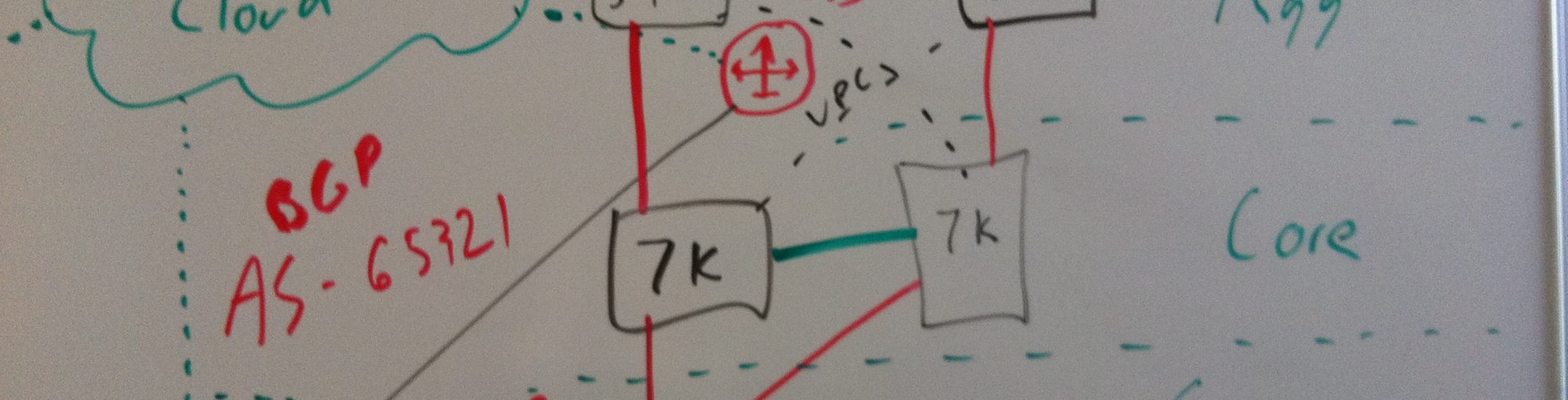
So just to level set, here is what our lab looks like…

We touched on the topic of pod IP addressing before, but let’s provide some background so that we’re all on the same page. The Kubernetes network model dictates that the containers off each Kubernetes node should be routable. Recall that the default docker network mode provides a docker0 bridge with IP address in the 172.17.0.0/16 range. Each container will get an IP out of this subnet and use the docker0 bridge IP (172.17.42.1) as it’s default gateway. The catch is that the network doesn’t need to know about 172.17.0.0/16 or how to get to it since the docker host does a IP masquerade (or hide NAT) behind it’s real NIC’s IP address for any traffic sourced from a container. That is, the network would see any container traffic as coming from the docker nodes physical IP address.
Note: When I use the work ‘network’ in this post I’m almost always referring to the physical network that connects the hosts together.
While this makes sense from an ease of use perspective, it’s not really ideal. That model requires all sorts of port mapping and in general sort of limits the ability of the docker host. In the Kubernetes model, the docker0 bridge on each host is routable on the network. That is, when a pod get’s deployed, a host outside of the cluster can access that pod directly rather than through a port mapping on the physical host. With that being said, you can view the Kubernetes nodes as routers from a network perspective. If we changed our lab diagram to a network diagram it might look more like this…

The multilayer switch (MLS) has two layer 3 segments hanging off of it. One supporting the 10.20.30.0/24 network and the other supporting the 192.168.10.0 /24 network. In addition, it has routes on it that tell it how to get to each of the subnets that hang off of the routers (Kubernetes nodes). This also means that containers generated on any node will use the node (docker0 bridge IP) as their default gateway, and the node in turn uses the MLS as it’s default gateway. I’m sort of beating the crap out of this concept but it’s important. Network guys LIKE layer 3 to the edge.
So now let’s move onto some examples and see what Kubernetes does on the networking side of things during different circumstances…
Deploying a pod
We did this in the last post, but let’s do it again and pay closer attention to what happens. Let’s take our pod example from the last post and use it again…
id: "webpod"
kind: "Pod"
apiVersion: "v1beta1"
desiredState:
  manifest:
    version: "v1beta1"
    id: "webpod"
    containers:
      - name: "webpod80"
        image: "jonlangemak/docker:web_container_80"
        cpu: 100
        ports:
          - containerPort: 80
            hostPort: 80
      - name: "webpod8080"
        image: "jonlangemak/docker:web_container_8080"
        cpu: 100
        ports:
          - containerPort: 8080
            hostPort: 8080
labels:
  name: "web"
Let’s also assume we’re working with a blank slate on the master. I’ve cleaned up any of the replication controllers, pods, and other services that we had used in the previous post…

So let’s go check out one of the nodes and see what it has running at this point. Let’s just pick kubminion1 for now…

So no containers running yet and I just want to point out the network configuration is as expected. We have a docker0 bridge interface and the minions local IP interface. Let’s head back to the master, deploy our pod from the config above, and see what happens…

So a couple of interesting things happened already. Kubernetes has assigned a host of 10.20.30.62 (kubminion1) for this pod to run on. Notice that the pod also has an IP address assigned to it which happens to be within the docker0 bridge allocation for kubminion1. Let’s pop over to kubminion1 and see what’s going on…

Kubminion1 now has 3 containers running. Our pod specification only defines 2, so where does the third one come from? The third containers is running and image called ‘kubernetes/pause:go’. Notice how this is the container that has the ports mapped to it as well. So why is that? Let’s take a deeper look at the containers to see why. I’m going to use the docker ‘inspect’ command to look at some of the information of each container. Namely, I want to see what network mode each container is deployed in…

Interesting, so if we check the ‘NetworkMode’ of each container we see an interesting configuration. The first container we inspected was running the ‘kubernetes/pause:go’ and has a default network mode. The second and third containers we inspected we’re running the ‘web_container_80’ and ‘web_container_8080’ images that we defined in our pods. Note that each of the pod containers has a non-default network config. Specifically, each pod container is using the mapped container mode and specifying the target container as the one running the ‘Kubernetes/pause:go’ image.
So let’s think about this for a second, why would they do this? First off, all the containers in the pod need to share the same IP address. This makes mapped container mode almost a requirement. However, why don’t they just start the first pod container, and then link the second pod container to the first? I think the answer to that question comes in two pieces. First, linking a pod that has multiple containers could be a pain if you had more than 2. Second, you’re dependant on the first container you linked to. If container 2 is linked to container 1, and container 1 dies, then the network stack on container 2 dies as well. It’s easier (and smarter) to have a very basic container run and link all of the pod containers to it. This also simplifies port mapping as we only ever need to apply port mapping rules to the pause container.
So our pod network diagram looks like this…

So the real network destination for the pod IP traffic is the pause container. The diagram above is a little deceiving since it shows the pause container ‘forwarding’ the port 80 and port 8080 traffic to the relevant containers. The pause container doesn’t actually do this, it just works that way logically since the two web containers are listening on those ports and share the same network stack with the pause continuer. This is why all of the port mappings for the actual pod containers show up under the port mapping for the pause container. We can examine this with the ‘docker port’ command…

So the pause container really just holds the network endpoint for the pod. It really doesn’t do anything else at all. So what about the node? Does it need to do anything to get the traffic to the pause container? Let’s check the iptables rules and see…

There are some rules here, but none of them apply to the pod we just defined. Like I mentioned in the last post, there are some default services Kubernetes provides by default which will be present on each Kubernetes node. That’s what we’re seeing in the above output. The key piece is that we don’t see any masquerade rules or any inbound port mappings for the pod 10.10.10.2.
Deploying a service
So now that we’ve seen how Kubernetes handles connecting it’s most basic building block, let’s talk about how it handles services. Like we talked about in our last post, services allow you to abstract services being hosted in pods. In addition, services allow you to scale services horizontally by providing a load balancing mechanism across pods hosting the same service. So let’s once again reset the lab by deleting the pod we just just created and make sure that kubmasta thinks the slate is clean…
 Now, let’s take the service we defined in the last post and examine it one more time. Here is the configuration file for the service we had called ‘myfirstservice’…
  id: "webfrontend"
  kind: "Service"
  apiVersion: "v1beta1"
  port: 80
  containerPort: 80
  selector:
    name: "web"
  labels:
    name: "webservice"
To make things a little clearer to explain, I’m going to change the service definition slightly to this…
  id: "webfrontend"
  kind: "Service"
  apiVersion: "v1beta1"
  port: 80
  containerPort: 8080
  selector:
    name: "web8080"
  labels:
    name: "webservice"
Exact same deal, just changed the container port to be 8080. So let’s define this service in the Kubernetes cluster..
Note: I dont think I mentioned this before but services should be built before pods that match the service selector are deployed. This ensures that the service related environmental variables exist in the containers.

The service creation worked as expected. If we check the available services we see that the cluster has given the service an IP address of 10.100.64.250. This IP address is allocated out of what Kubernetes refers to as the ‘Portal Network’. If you recall, when we built the API service on the kubmasta one of the flags we defined was the ‘PortalNet’…
[Unit]
Description=Kubernetes API Server
After=etcd.service
Wants=etcd.service
[Service]
ExecStart=/opt/kubernetes/kube-apiserver \
--address=0.0.0.0 \
--port=8080 \
--etcd_servers=http://127.0.0.1:4001 \
--portal_net=10.100.0.0/16 \
--logtostderr=true
Restart=on-failure
RestartSec=5

[Install]
WantedBy=multi-user.target
This can really be any subnet so long as it doesn’t overlap with the docker0 or physical host subnets. The reason that it can be any subnet is that it’s never routed on the network. The portal net is only locally significant to each node and really just a means to get the traffic off the container and headed towards its default gateway (the docker0 bridge). So before we go any further, let’s again look at kubminion1 and see what’s changed since we defined the service. Let’s start by checking the netfilter rules…
Note: I’m talking about the same service as above but the IP address is different. This is an unfortunate side effect of writing this blog over a few days and having to rebuild pieces of the lab in between. Above I refer to the service IP as 10.100.64.250 and below I refer to it as 10.100.87.105. Sorry for the confusion!

So what do these rules do? The first line tells the host to match a TCP flow destined to 10.100.87.105 on port 80. If it sees a flow that matches that specification, it should redirect the traffic locally to port 39770. The second line tells the node to do the same thing but in a different manner since you’re covering traffic generated from the host rather than the container. The reason the rule isnt identical is because REDIRECT only works for traffic that’s traversing the host. Traffic that’s generated by the host needs to be tackled with a DNAT rule. Long story short, they accomplish the same thing just in different ways so that all traffic coming off the node headed to 10.100.87.105 on port 80 get redirected locally to the host on port 39770.
So we know that any traffic destined to the service IP and port will get redirected to the localhost on port 39770. But where does that get us? This is where the kubernetes-proxy service comes into play. The proxy service assigns a random port for a newly created service and creates a load balancing object within the service that listens on that particular port. In this case, the port happened to be 39770. If we would have been watching the logs of the kuberenetes-service on kubminion1 when we created the service, we would have seen log entries like this…

So now that the traffic destined to the service is being redirected to the proxy, we need something for it to load balance to. Let’s spin up one of the replication controllers from our last blog so we can see this in action. I’ll use this config for my replication controller…
id: web-controller-2
apiVersion: v1beta1
kind: ReplicationController
desiredState:
  replicas: 4
  replicaSelector:
    name: web8080
  podTemplate:
    desiredState:
      manifest:
        version: v1beta1
        id: webpod
        containers:
          - name: webpod
            image: jonlangemak/docker:web_container_8080
            ports:
              - containerPort: 8080
    labels:
      name: web8080
Let’s load this into the cluster and make sure that all of the pods start…

Looks good. So now that we have all the pods running, the service should select pods for load balancing that match the label of ‘web8080’. Since the replication controller selector matches all of the pods with the label of ‘web8080’, we should have 4 pods to load balance against. At this point, I’d argue that our lab looks like this…

While the Kubernetes proxy has been depicted as a sort of shim, it’s really just another service running on the node. The redirect rules we saw above are what make the Kubernetes proxy a shim for traffic destined to service IP addresses.
To see this in action, we’ll do a series of packet captures using tcpdump. To do this, we need to install tcpdump on kubminion1. Let’s install it with this command…
yum -y install tcpdump
Once installed, let’s open three SSH sessions to kubminion1. In the first window we’ll run the following tcpdump command…
tcpdump -nn -q -i ens18 port 8080
Note: In this case we want to capture packets on the servers physical ethernet interface. In my case, it’s called ‘ens18’.
In the second window we want to run another tcpdump, but we need to get some more info first. Namely, we want to get the virtual interface (veth) name for the container attached to the docker0 bridge. Running with the assumption that you only have the webpod container running on this host you can do a simple ‘ifconfig’ and you should only have one ‘Veth’ interface…

Copy this interface name and insert it into the tcpdump command for your second window…
tcpdump -nn -q -i veth12370a6 host 10.100.87.105
Run both the commands and stack the windows up so you can see both at the same time…

So once you have both captures running let’s turn our attention to the third window. Let’s use our ‘docker exec’ command to attach into the ‘web_container_8080’ container (do a ‘docker ps’ to get the container name first)…
docker exec -it e130a52dfae6 /bin/bash
Once inside the running container, let’s try and access the service with curl…
curl 10.100.87.105
After my first curl to the service IP address, I had this in my capture windows…

So what does this tell us? Let’s draw this out in our diagram showing the top capture (traffic off the servers physical NIC) in red and the bottom capture (traffic off the docker0 bridge) in blue…

Note: I make a point to draw the line around the ‘kubernetes proxy’ on kubminion3. I did this because the kubernetes proxy on kubminion3 is NOT required for this flow to work. Put another way, the proxy service that intercepts the service request talks directly to the pod it load balances to.
So if we look at the bottom window first, we see the traffic from the container point of view. The container attempts to open a TCP socket to 10.100.87.105 on port 80. We see return traffic from the service IP address of 10.100.87.105. From the container’s point of view, it’s entire communication is with the service. If we look at our second capture (top window) we can see what actually hit the wire. We see a TCP session sourced from the nodes physical IP address (10.20.30.62) and destined to the pod hosted on kubminion3 (10.10.30.4). To summarize, the Kubernetes proxy service is acting as a full proxy maintaining two distinct TCP connections. The first from container to proxy, and the second from proxy to the load balanced destination.
If we cleared our captures and ran the curl again we should see the traffic load balanced to another node…

In this case, the Kubernetes proxy decided to load balance the traffic to the pod running on kubminion2 (10.10.20.4). Our diagram for this flow would look like…

I think you get the point without me showing you the other two possible outcomes for load balancing our test service. The important part to understand about services is that they allow you to easily and quickly scale pod deployed services. One could see how this can be a powerful feature when coupled with pods deployed with a replication controller.
But while services handle an important aspect of a Kubernetes cluster, they’re only relevant for pods accessing services living in other pods. Recall, the portal IP space isn’t accessible from the network, it’s only locally significant to the host. So how do things outside the cluster consume applications deployed in the cluster? We’ll cover that in our next post.
Very helpful in understanding the network structure underlying Kubernetes, thanks a lot!
I missed the link between the first service IP you referenced (10.100.64.250) and what shows up as the balancing IP on kubminion1 (10.100.87.105).
Or is this a typo, and 10.100.87.105 is the correct service IP?
Ah – Good catch. I think I see what happened. I wrote this post over a 2 day period of time and I think I likely had to rebuild the service halfway through. I’ll add a note to clarify this in the post, thanks for catching it!
Very useful – I particularly appreciated seeing the NetworkMode details as this explained how localhost is shared within a pod (but only outside a pod if explicitly mapped with ports settings in the container YAML spec
What the flow will be like if the container has no host port but just has container internal port? My guess is the kubernetes proxy on kubminion03 will handle the connection with kubernetes proxy on kubminion01 in the first example in your article. Is that right? Thanks.
Awesome!! Very helpful. Thanks a lot. Indeed it clears the air on Kubernetes services
Pingback: Docker / Devops Sites | pushthings
Dont we configure probe for health on service ? How that will be handled when RC added new pod?
Awesome, awesome read. If I could put in a request for a future writeup (since I’m so impressed with this and others on your site): Subnetting and Docker Networking for Developers. Docker and Kubernetes are principally aimed at Developers. Yes, Docker’s “configure once, run anything” paradigm makes things groovy for Operations, but you’ll never see an Operations Team at the avergae enterprise say “Hey! Let’s set up Docker/Kubernetes for all future workloads!” The impetus of change from VM -> Docker will almost *always* come from Developers. Ergo it will usually be the Developers setting up Docker/Kubernetes themselves, at the very least in some non-production “sandbox” environment to test things out.
The problem here is that Developers are networking dummies for the most part. You and the world-class Devs at Google might be exceptions here, but the average developer will choke hard when trying to build Kubernetes from scratch and define all the networking (subnetting and flat namespacing, etc.) required by Kubernetes’ networking model. I know I am (choking hard)!
So if you could have an introductory article, explaining:
* Subnetting
* Docker’s networking model, and why Kubernetes’ model is superior
I think that would be…the best thing of all time…ever.
Thanks for putting so much time into this, helped me out enormously!
Thanks for reading and for the comments!
Can you clarify what you’d be looking for in a subnetting article? I’d love to hear what aspects of subnetting you as a developer would like to know more about. That would give me some great direction to build off of.
As far as the network model itself, that’s sort of hard to quantify. When I think about the Docker network model vs the Kubernetes model I think about it in tiers. Docker is this ‘thing’ that provides many different configuration options. Kubernetes builds on that by consuming the Docker network constructs in clever ways through the API. Long story short, each has their own merits and use cases. The delineation occurs at a higher level with the question being ‘Do you need a scheduler?’. If so, I think Kubernetes has the network model mostly sorted out.
Would love to hear any other thoughts you have on the matter.
Thanks!
In the 2nd picture, the IP of kubbuild should be .60, not .62.
Updated! Thanks for the catch!
Pingback: Learn the Kubernetes Key Concepts | IT with Passion
I am really impressed with the details this article has been written, one dumb question,
Kube-proxy is only used to load balance traffic from inside to outside, not vice-versa??
This is an AMAZING article, kudos to you sir!
Thanks for valuble inforamtion. 🙂
How can capture traffic inside the POD? all the containers have NetworkMode to “pause” container. So, is there any way to capture the traffic? For example: There a mysql and apache in a POD, and they have communication.
Thanks
Thank you for the article. Just one question is about 10.100.0.0/16. How service users will get to the network? Probably MLS should have another one route looks like: ip route 10.100.0.0 255.255.0.0 X.X.X.X. Where X.X.X.X any node with kubernetes-proxy service. Here we get a dilemma what node should we choose without forgetting redundancy in the infrastructure? Any ideas?
This was really helpful, specifically in demystifying the pod concept. Thanks a ton.
Great blog, Jon.
When you execute the curl command, are the pause:go container ports randomly chosen per request, it looks like it from your tcp dumps? Also, am I right to assume that it’s the kube-proxy that sends the curl request to web_container_8080, and that the request is also sent from a randomly chosen port per request?
http://www.sysdig.org/ looks useful, if you haven’t already tried it. Keep up the good work!
Very nice article, Das. Here is something I think you might add to your next article (now that we are in OpenShift era).
1) How the basic Kubernetes networking requirement is satisfied? In other words, how the Node knows where the destination Pod is? In this case, Node 10.20.30.62 and the MLS (or underlay network) has to know how to reach 10.10.30.2 Pod. You noted static IP routes on MLS, but showed nothing about the routing table on Node.
2) Kubernetes Networking page shows a few options such as using OVS, Flannel, OVN, Calico, etc. You can discuss the OVS method first, and if time permits write about Flannel, Calico, or OVN networking. Also, discuss about pros and cons of using overlay models and underlay models.
Great article. Thank you for posting!
Pingback: Kubernetes是什么-Wikipedia | 酷 壳 – CoolShell 3F