In our last post, we removed our last piece of static configuration and replaced static routes with BGP. We’re going to pick up right where we left off and discuss another use case for MPLS – MPLS VPNs. Really – we’re talking about two different things here. The first is BGP VPNv4 address families used for route advertisement. The second is using MPLS as a data plane to reach the prefixes being announced by VPNv4 address family. If that doesn’t make sense yet – don’t worry – it will be pretty clear by the end of the post. So as usual – let’s jump right into this and talk about our lab setup.
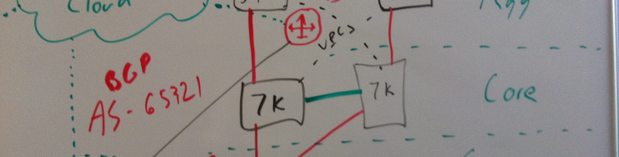
As I mentioned in the last post, setting up BGP was a prerequisite to this post – so since that’s the case – Im going to pick up right where I left off. So I’ll post the lab topology picture here for the sake of posting a lab topology – but if you want to get your configuration prepped – take a look at the last post. At the end of the last post we had our two clients talking to one another using MPLS as the data plane forwarding mechanism and BGP as the route or prefix advertisement mechanism.

To do this – we peered router 1 to router 4 with BGP and let them advertise the directly connected prefixes that met a prefix-list based filter. This worked great and removed the need for us to use static routes to force a recursive routing lookup into the inet.3 table so that we could use MPLS labels for forwarding. But now what happens if we want to support more than one tenant? Let’s say that Im running an ISP and I want to provide connectivity between different endpoints in the network for different tenants. And what if those tenants use the same IP networks? The only way to solve that problem is to provide a means of layer 3 isolation on my network so each tenant can stay isolated. So in our example above, let’s say that client 1 and client 2 are members of company ABC and we’re tasked with providing them an isolated path across my amazing 4 router backbone network. To do this, there are 2 main problems we have to solve.
- Distributed L3 Isolation – How do we extend that isolation across the backbone so that company ABC can reach all of their locations?
- Local L3 Isolation – How do we provide local isolation on the router where the client enters the backbone?
So let’s tackle these problems one at a time.
Distributed L3 isolation
Up until now we’ve been using the default or global table on each router to provide routing functionality. If we look at the routing-table on the router 1 we’ll see all of the OSPF based loopback addresses as well as the remote BGP prefix we learned from router 4…
root@vmx1> show route table inet.0

inet.0: 15 destinations, 15 routes (15 active, 0 holddown, 0 hidden)
+ = Active Route, - = Last Active, * = Both

1.1.1.1/32         *[Direct/0] 1w5d 23:43:06
                    > via lo0.0
2.2.2.2/32         *[OSPF/10] 1w5d 23:38:00, metric 1
                    > to 10.1.1.1 via ge-0/0/1.0
3.3.3.3/32         *[OSPF/10] 1w5d 23:38:00, metric 2
                    > to 10.1.1.1 via ge-0/0/1.0
4.4.4.4/32         *[OSPF/10] 1w5d 23:38:00, metric 3
                    > to 10.1.1.1 via ge-0/0/1.0
10.1.1.0/31        *[Direct/0] 1w5d 23:40:14
                    > via ge-0/0/1.0
10.1.1.0/32        *[Local/0] 1w5d 23:40:14
                      Local via ge-0/0/1.0
10.1.1.2/31        *[OSPF/10] 1w5d 23:38:00, metric 2
                    > to 10.1.1.1 via ge-0/0/1.0
10.1.1.4/31        *[OSPF/10] 1w5d 23:38:00, metric 3
                    > to 10.1.1.1 via ge-0/0/1.0
10.2.2.0/31        *[Direct/0] 00:00:09
                    > via ge-0/0/0.0
10.2.2.0/32        *[Local/0] 00:00:09
                      Local via ge-0/0/0.0
10.2.2.2/31        *[BGP/170] 1w0d 05:35:22, localpref 100, from 4.4.4.4
                      AS path: I, validation-state: unverified
                    > to 10.1.1.1 via ge-0/0/1.0, Push 299936
10.20.30.0/24      *[Direct/0] 1w5d 23:54:33
                    > via fxp0.0
10.20.30.135/32    *[Local/0] 1w5d 23:54:33
                      Local via fxp0.0
224.0.0.2/32       *[LDP/9] 12w5d 16:29:55, metric 1
                      MultiRecv
224.0.0.5/32       *[OSPF/10] 9w4d 13:47:19, metric 1
                      MultiRecv

root@vmx1>
Bottom line – we’re dealing with a common routing table. To provide isolation, we’ll need to fix this. So the first thing we need to do is figure out how we do this with BGP. At the moment, BGP is talking between router 1 and router 4 in the default or global table. Prefixes it advertises to other peers live here and prefixes it learns land here. So let’s back up a second. We know that we want to support multiple customers – and those customers could use the same prefixes – so how can we possibly have BGP advertising the same prefixes for different customers? The answer comes in the form of VPNv4 prefixes. You see – to make a routing advertisement unique, VPNv4 prefixes just add additional distinguishing information onto a route advertisement. This distinguishing information is aptly called a “route distinguisher” or more commonly just an “RD”. And RD is a 64 bit value that prefaces a customers routing advertisement. For instance…

You can see above that to make a standard prefix a VPNv4 prefix we simply preface it with an RD. That RD can come in three different forms…

The form you use doesn’t matter much but you should use the same form for consistency sake. So now the question becomes, how do we get BGP to send and understand VPNv4 prefixes? To do that, we need to activate a new address family – VPNv4. This is easy to do, we simply enable the inet-vpn family under the ibgp group we created earlier…
[edit]
root@vmx1# set protocols bgp group ibgp family inet-vpn unicast

[edit]
root@vmx1# commit
commit complete

[edit]
root@vmx1# show protocols bgp
group ibgp {
    type internal;
    family inet {
        unicast;
    }
    family inet-vpn {
        unicast;
    }
    export mpls_bgp;
    peer-as 65000;
    neighbor 4.4.4.4 {
        local-address 1.1.1.1;
    }
}

[edit]
root@vmx1#
Let’s add the same change to router 4 as well – set protocols bgp group ibgp family inet-vpn unicast
So now what? Surprisingly, that’s sort of it. Feel like you missed something? Don’t worry! It will all come together soon, but we need to tackle the next task of providing local L3 isolation before we can see any real progress. So let’s get that out of the way and then see where we stand.
Local L3 Isolation
Providing local layer 3 isolation on a router is pretty simple thing to do in most cases. Both Juniper and Cisco allow you to define VRF (Virtual Routing and Forwarding) instances which create isolated routing tables. You can then add interfaces from the router/switch into a given VRF. By default, all interfaces live in the default (sometimes called global) routing table. Moving them to a VRF removes them from the default routing table and places them in the VRF’s routing table. Let’s take a look at what it would take to add a Company ABC VRF on router 1 and 4 so I can show you what I mean.
Even in this mode, where we are just defining local VRFs (sometimes called VRF-lite mode), there are some differences in how you define them between Juniper and Cisco. In Cisco – a VRF is a VRF regardless if you’re using it locally or intend to use it in conjunction with something like MPLS and VPNv4. On a Juniper, there are two routing-instance types for VRFs. One for VRF-lite mode and one for using VRFs in conjunction with VPNv4…
root@vmx1# set routing-instances company_abc instance-type ?
Possible completions:
  evpn                 EVPN routing instance
  evpn-vpws            EVPN VPWS routing instance
  forwarding           Forwarding instance
  l2backhaul-vpn       L2Backhaul/L2Wholesale routing instance
  l2vpn                Layer 2 VPN routing instance
  layer2-control       Layer 2 control protocols
  mpls-forwarding      Routing instance provides a MPLS forwarding-context
  mpls-internet-multicast  Internet Multicast over MPLS routing instance
  no-forwarding        Nonforwarding instance
  virtual-router       Virtual routing instance
  virtual-switch       Virtual switch routing instance
  vpls                 VPLS routing instance
  vrf                  Virtual routing forwarding instance
[edit]
root@vmx1# set routing-instances company_abc instance-type
The two we’re going to concern ourselves with are types virtual-router and vrf. virtual-router defines the VRF-lite mode where the VRF is only local to the box. Since we know we want distributed isolation, we’re going to need to use the vrf instance type. Let me show you why. Here’s the definition of a simple routing-instance…
root@vmx1# show|compare
[edit]
+  routing-instances {
+      company_abc {
+          instance-type virtual-router;
+          interface ge-0/0/0.0;
+      }
+  }

[edit]
root@vmx1# commit check
configuration check succeeds

[edit]
root@vmx1#
Notice that the definition is incredibly simple. We define the name, the type, and the interface we want in it. This configuration is valid and passes a commit check. Let’s commit it and take a quick look around…
root@vmx1> show route table company_abc.inet.0

company_abc.inet.0: 2 destinations, 2 routes (2 active, 0 holddown, 0 hidden)
+ = Active Route, - = Last Active, * = Both

10.2.2.0/31        *[Direct/0] 00:00:43
                    > via ge-0/0/0.0
10.2.2.0/32        *[Local/0] 00:00:43
                      Local via ge-0/0/0.0

root@vmx1>
Once committed – we can see that we now have a new routing table on the router named company_abc.inet.0. That routing table has the prefixes associated with ge-0/0/0 in it. So if we look at the global or default routing table, we’ll notice these are now gone…
root@vmx1> show route table inet.0 10.2.2.0/31

root@vmx1>
So this means that any traffic that comes into this IP interface on this router will be only allowed to talk other prefixes in this table. At this point – there aren’t any. So how do we get some? BGP and it’s VPNv4 route advertisements to the rescue!
In the last section, we talked about the need for VPNv4 routes, and we learned how to enable them in BGP, but we didnt really define any. That’s because RD’s are defined as part of a routing-instance. Here’s where we’ll see the difference between the virtual-router and the vrf instance type with Juniper. If we try to define an RD in our existing routing-instance, we’ll see this…
root@vmx1# commit check
[edit routing-instances]
  'company_abc'
    RT Instance: Route-distinguisher cannot be configured for virtual-router instance: company_abc
error: configuration check-out failed

[edit]
root@vmx1#
So as it turns out we need to use the vrf instance-type in order to define an RD. So let’s change our configuration to look like this…
root@vmx1# show routing-instances
company_abc {
    instance-type vrf;
    interface ge-0/0/0.0;
    route-distinguisher 65000:150;
}

[edit]
root@vmx1#
Notice we changed the type to vrf and added a route-distinguisher of 65000:150. Now if we try and commit this we’ll see…
root@vmx1# commit
[edit routing-instances]
  'company_abc'
    RT Instance: vrf-import or vrf-target must be configured for vrf instance company_abc
error: configuration check-out failed

[edit]
root@vmx1#
So now it also wants a route target. What’s that all about? I mean – we already made the routes unique by tacking on an RD. So what purpose does a route-target serve? Route targets (known as RTs) are what is actually used to make policy decisions about a prefix. Whereas RDs serve only to make a quote unique – RTs are the gate keepers to a VRF and what the router uses to decide what route advertisements can/should go where. What often confuses people is that the definition of an RT and RD can be identical if you wish. For the sake of this lab we’ll make them different but do note that they follow the same type definition/format as RDs as we showed in the earlier section. So let’s add an RT to our definition…
root@vmx1# show routing-instances
company_abc {
    instance-type vrf;
    interface ge-0/0/0.0;
    route-distinguisher 65000:150;
    vrf-target target:65000:151;
}

[edit]
root@vmx1#
Once again – let’s now make the same similar changes on router 4 (I’ll provide these in set syntax so you can see the actual commands I used)…
Note that in my lab the customer facing interface for client 1 and client 2 differs so you can’t copy and paste this configuration to both routers without changing the interface.
set routing-instances company_abc instance-type vrf
set routing-instances company_abc interface ge-0/0/1.0
set routing-instances company_abc route-distinguisher 65000:150
set routing-instances company_abc vrf-target target:65000:151
So now that this is all in place – we can do some validation. Let’s start on router 1…
root@vmx1> show bgp summary
Groups: 1 Peers: 1 Down peers: 0
Table          Tot Paths  Act Paths Suppressed    History Damp State    Pending
inet.0
                       0          0          0          0          0          0
bgp.l3vpn.0
                       0          0          0          0          0          0
Peer                     AS      InPkt     OutPkt    OutQ   Flaps Last Up/Dwn State|#Active/Received/Accepted/Damped...
4.4.4.4               65000        510        509       0       4     3:46:07 Establ
  inet.0: 0/0/0/0
  bgp.l3vpn.0: 0/0/0/0

root@vmx1>
Notice that under the peer4.4.4.4 we now see the additional bgp.l3vpn.0 family. The fact that its listed under the peer tells us that router 1 has negotiated this functionality with router 4. In other words – they’re talking VPNv4 at this point. We can also see what prefixes are being advertised by router 1…
root@vmx1> show route advertising-protocol bgp 4.4.4.4

company_abc.inet.0: 2 destinations, 2 routes (2 active, 0 holddown, 0 hidden)
  Prefix		  Nexthop	       MED     Lclpref    AS path
* 10.2.2.0/31             Not advertised               100        I

root@vmx1>
Above we can see that for the BGP peering to router 4 (4.4.4.4) router 1 lists the 10.2.2.0/31 prefix as part of the company_abc.inet.0 table. However – notice that the next-hop of this prefix is listed as Not Advertised. We can confirm that this is not being advertised by running a similar command on router 4…
root@vmx4> show route receive-protocol bgp 1.1.1.1 extensive

inet.0: 12 destinations, 12 routes (12 active, 0 holddown, 0 hidden)

inet.3: 3 destinations, 3 routes (3 active, 0 holddown, 0 hidden)

company_abc.inet.0: 2 destinations, 2 routes (2 active, 0 holddown, 0 hidden)

mpls.0: 10 destinations, 10 routes (10 active, 0 holddown, 0 hidden)

inet6.0: 1 destinations, 1 routes (1 active, 0 holddown, 0 hidden)

root@vmx4>
We can see here that router 4 is not receiving any prefixes from router 1 (1.1.1.1). So what’s going on? Shouldn’t this all work? Let’s take a closer look at the advertised routes on router 1 by tacking on the extensive keyword to the advertised routes command…
root@vmx1> show route advertising-protocol bgp 4.4.4.4 extensive

company_abc.inet.0: 2 destinations, 2 routes (2 active, 0 holddown, 0 hidden)
* 10.2.2.0/31 (1 entry, 1 announced)
 BGP group ibgp type Internal
     Route Distinguisher: 65000:150
     BGP label allocation failure: Need a nexthop address on LAN
     Nexthop: Not advertised
     Flags: Nexthop Change
     Localpref: 100
     AS path: [65000] I
     Communities: target:65000:151

root@vmx1>
Huh – So its saying that it failed to allocate a next-hop address on LAN. What does that mean? Let’s take a step back and talk about what’s going on right now and see if we can sort this out.
We mentioned earlier that there were two separate goals here. One was to enable Distributed L3 isolation across our MPLS cloud and the second was to do it locally on each router that clients connect to. We talked about how to enable BGP to advertise unique prefixes per customer (or VPN) but we didn’t talk about how that ties into MPLS to make a working data plane. So how does this all work together? The answer comes in the form of a label stack. Let’s talk through what we think should be happening and then see if we can validate this in the lab.
So the first thing we need to know is that MPLS labels can be stacked. In all of our previous posts, there was a single MPLS label and it was swapped at each MPLS hop. This is how MPLS forwards traffic. Adding more than one label opens up some interesting possibilities in terms of applications. In the case of VPNv4 route advertisements, it means I can tell remote peers about an additional label. So let’s walk through how this might work…

The picture above shows two label advertisements. The first is the LDP label advertisement shown with the blue arrows. As we saw in the post on LDP this label distribution occurs hop by hop and each label is locally significant. In this case, router 4 is telling router 3 – “If you want to get to an LSP that ends at me (4.4.4.4) send me a frame with a top label of 3”. Router 3 records that request in it’s local label database – and then tells it’s other LDP peers about this. Router 3 tells router 2 – “If you want to get to an LSP that ends at router 4 send me a frame with the top label of 299808”. And finally – router 2 tells router 1 – “If you want to get to an LSP that ends at router 4 send me a frame with the top label of 299936”. This is how LDP works and it’s well described in the earlier post. What’s new is the green line shown above. This is a label allocated and learned by BGP and advertised to all VPNv4 capable BGP peers. So how does this new label work?
- When the top client wants to talk to the bottom client it will send traffic to router 1. That interface is part of a local VRF (
company_abcVRF) on the router and that VRF has an associated RD and RT. - Router 1 will do a route lookup in the
company_abcrouting table and see if it has a matching destination prefix for the traffic. In this case, it would have learned the prefix10.2.2.2/31through BGP (specifically through the BGP VPNv4 advertisements). If we examine that advertisement sent by router 4 for10.2.2.2/31we should see that the advertisement includes a VPN label. - This VPN label will be pushed onto the frames label stack first. Since the LSP for this traffic still ends at router 4 – the LDP based label will then also be pushed on the label stack.
- When router 2 receives the MPLS frame, it will only process the top label leaving the bottom label (the VPN label in this case) intact. Router 2 will process the frame, swap the top label, and send it on it’s way.
- Each subsequent MPLS hop will do the same thing only dealing with the top label
The flow looks like this…

Pretty slick huh? Notice that since router 4 had sent router 3 the label of 3 (Implicit Null) to reach 4.4.4.4 router 3 has obliged and popped the top label off of the stack. In a scenario without MPLS VPNs, this would mean that router 4 would receive a native Ethernet frame and IP packet. However – even after popping the top label we still have the VPN label to contend with. This puts us in a little bit of a unique scenario and helps describe why things aren’t currently working. In a typical MPLS configuration, the clients would more likely be CE or Customer Edge routers. Router 1 and router 4 would be serving as PEs or Provider Edge routers. In that scenario it is almost guaranteed that router 1 and router 4 would be routing to reach remote prefixes. That is the link between the PE and the CE would be a transit network and the PE would be learning prefixes over some sort of dynamic routing protocol from the CE. In that scenario, JunOS can advertise a label for each potential next hop address it needs to talk to. That means when it receives a frame with a VPNv4 label it can directly translate this to a next hop and forward the packet. In our case – the destinations are directly attached to a multi-access network. This means that the next-hop is not well known and that the router will need to perform normal ARP discovery to find the MAC address for the destination. So rather than a label to next hop direct mapping, we’re asking the router to perform two different actions when it receives a VPNv4 labelled frame. First it has to use the VPN label to determine what VRF the traffic should land in – then it needs to ARP to find the destination. That is why this is currently not working – the routers recognize that this is a problem and therefore wont allocate a VPNv4 label for the customer prefix. Hence the message Need a nexthop address on LAN. There are a couple of ways to solve this and this Juniper article does a good job explaining them. In our case, we’re going to use the vrf-table-label command to fix this. In addition to changing the label allocation method for VPNv4 prefixes – this also allows traffic to be recirculated on the router so that the VPN label can be popped and the ARP process can happen. So let’s add the following configuration to router 1 and router 4…
set routing-instances company_abc vrf-table-label
Now if we try to ping client 1 from client 2 – we should see it’s working as expected…
user@client2:~$ ping 10.2.2.1 -c 3
PING 10.2.2.1 (10.2.2.1) 56(84) bytes of data.
64 bytes from 10.2.2.1: icmp_seq=1 ttl=60 time=2.98 ms
64 bytes from 10.2.2.1: icmp_seq=2 ttl=60 time=2.91 ms
64 bytes from 10.2.2.1: icmp_seq=3 ttl=60 time=2.70 ms

--- 10.2.2.1 ping statistics ---
3 packets transmitted, 3 received, 0% packet loss, time 2001ms
rtt min/avg/max/mdev = 2.707/2.869/2.986/0.126 ms
user@client2:~$
Let’s look at what’s happening in more detail…
root@vmx1> show route advertising-protocol bgp 4.4.4.4 extensive

company_abc.inet.0: 3 destinations, 3 routes (3 active, 0 holddown, 0 hidden)
* 10.2.2.0/31 (1 entry, 1 announced)
 BGP group ibgp type Internal
     Route Distinguisher: 65000:150
     VPN Label: 16
     Nexthop: Self
     Flags: Nexthop Change
     Localpref: 100
     AS path: [65000] I
     Communities: target:65000:151

root@vmx1>
Notice that router 1 now shows it is advertising the prefix to router 4. Also note that it’s allocated a VPN label of 16 to use for this VRF. The other impact that vrf-table-label has is that it allocates a single label for all prefixes for a given VRF (which makes way more sense given the command you entered). So that means that all prefixes on router 1 that are a part of company_abc VRF will be advertised with a label of 16 to router 4. Let’s look and see what we learned from router 4…
root@vmx1> show route table company_abc.inet.0

company_abc.inet.0: 3 destinations, 3 routes (3 active, 0 holddown, 0 hidden)
+ = Active Route, - = Last Active, * = Both

10.2.2.0/31        *[Direct/0] 18:30:33
                    > via ge-0/0/0.0
10.2.2.0/32        *[Local/0] 18:30:33
                      Local via ge-0/0/0.0
10.2.2.2/31        *[BGP/170] 00:04:19, localpref 100, from 4.4.4.4
                      AS path: I, validation-state: unverified
                    > to 10.1.1.1 via ge-0/0/1.0, Push 16, Push 299936(top)

root@vmx1>
Here we can see that to reach the network 10.2.2.2/31 router 1 believes it should impose a bottom label of 16 and a top label of 299936. Just like we expected it would! Let’s verify that 16 is in fact the VPN label that router 4 sent to router 1….
Note: This can be the confusing things about small MPLS labs. Often times, the same label is allocated on different boxes. In our case – both router 1 and router 4 allocated a per VRF label of 16 for company_abc VRFs.
root@vmx1> show route receive-protocol bgp 4.4.4.4 extensive

inet.0: 12 destinations, 12 routes (12 active, 0 holddown, 0 hidden)

inet.3: 3 destinations, 3 routes (3 active, 0 holddown, 0 hidden)

company_abc.inet.0: 3 destinations, 3 routes (3 active, 0 holddown, 0 hidden)
* 10.2.2.2/31 (1 entry, 1 announced)
     Import Accepted
     Route Distinguisher: 65000:150
     VPN Label: 16
     Nexthop: 4.4.4.4
     Localpref: 100
     AS path: I
     Communities: target:65000:151

mpls.0: 11 destinations, 11 routes (11 active, 0 holddown, 0 hidden)

bgp.l3vpn.0: 1 destinations, 1 routes (1 active, 0 holddown, 0 hidden)

* 65000:150:10.2.2.2/31 (1 entry, 0 announced)
     Import Accepted
     Route Distinguisher: 65000:150
     VPN Label: 16
     Nexthop: 4.4.4.4
     Localpref: 100
     AS path: I
     Communities: target:65000:151

inet6.0: 1 destinations, 1 routes (1 active, 0 holddown, 0 hidden)

root@vmx1>
Lots of interesting information here. In the top section we can see that the company_abc routing table did receive an entry for 10.2.2.2/31 with a VPN label of 16, an RD of 65000:150, and next hop of router 4 (4.4.4.4). Notice that the RT is listed as a community on that advertisement. Recall that the RT is how we define routing policy in terms of what we import and export into a VRF. At this point – since we haven’t applied any import or export policy for the VRF – JunOS will happily receive and advertise all advertisements in a given VRF. We’ll look at this more in a later post.
The second section shows the entry in the bgp.l3vpn.0 table. This table stores all VPNv4 advertisements received by the router. In a later post where we look at having multiple customers on the same MPLS backbone we’ll see that all of their advertisements land in this table before specific entries make it into the customer specific VRF tables. So I think we can safely update our digram to look like this…

Last but not least, lets do some packet captures to validate this is actually whats hitting the wire…
ICMP echo request on the wire between routers 1 and 2…

ICMP echo request on the wire between routers 2 and 3…

ICMP echo request on the wire between routers 3 and 4…

The capture confirms the flow we described in the diagram perfectly! In the above captures – the first label listed (top down) is the top label. You can also tell that the VPN label of 16 is the bottom label since that label has the bottom of the label stack bit set to 1. Notice that in the capture between router 3 and 4 we only have one label. Recall that router 4 is asking router 3 to perform PHP to remove the LDP label before forwarding it the frame.
This has been a warp speed tour of MPLS VPNs and we relied on lots of the default functionality to make this work. In the next post, I hope to cover more specifics about VRF import and export based on the RTs. Stay tuned!
A very good write up Jon. Paul and I will have to point some of our engineers toward this article. Thanks!